1.Introduction
Modern technology products increasingly require hardware miniaturization and stringent power efficiency. In the display industry, key components such as light engines and waveguide optics must be optimized to deliver high performance while meeting the size and power constraints of next- generation display systems.
In the virtual reality (VR) and augmented reality (AR) industries, as devices become smaller, such as gaming headsets and smart glasses, these device requirements become even more critical. The difference between VR and AR is that in AR systems, displays are Optical-See-Through (OST) where digital elements are overlaid into the user’s real world field of view. By contrast, in VR systems, the entire environment is digital, replacing the real world as a simulated one, sometimes with a Video-See-Through (VST) approach.
This paper will focus on AR displays as used in Augmented Reality (AR) glasses. AR glasses are OST “wearable devices that incorporate AR technology to overlay digital content onto the user’s real-world view” [1]. Recently, audio focused glasses have been developed for consumer applications that have been limited to video capture of the surrounding environment with audio queries, providing only audio feedback to the user (such as Meta Ray-Ban). New developments in miniaturization of hardware and cost reductions in light engines and waveguides are now making rich visuals in AR glasses possible. With these advancements, AR glasses can be used for many applications:
- Multimodal agentic AI assistant – cameras and audio input on AI devices can aid in object recognition, memory enhancement, and relay information to the user
- Augmented navigation – real-time feedback for walking/driving overlaying directions and information about the surroundings
- Communication – real time language translation, facilitating video calls, allowing the user to share their physical environment
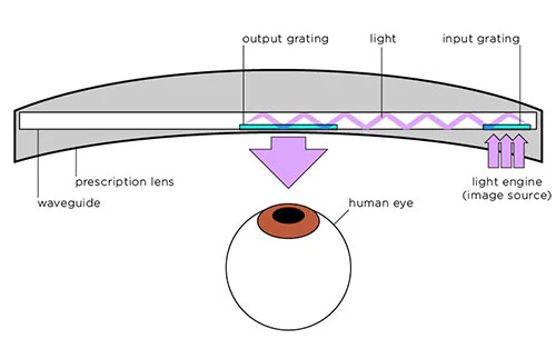
In general, AR displays consist of two main components: the light engine (and associated electronics/optics) for creating the image, and a waveguide to project/deliver the image to the eye. Figure 1 shows how these components work together in AR glasses.
The light engine projects an image into the input grating of the waveguide, which uses total internal reflection to redirect the image to the viewer’s eye through an output grating. Note the glasses can include a prescription correction lens also.
For the light engine of AR glasses, there are only two practical choices due to size and brightness required: Liquid Crystal on Silicon (LCoS) and Micro Light Emitting Diode (microLED).
2. MicroLED light engines
MicroLED technology as the light engine for AR glasses has caused quite a buzz in the industry in the last several years, with promises of high brightness, small sizes, fast response time, and high image quality. But this relatively new technology has some fundamental limitations in performance, along with significant manufacturing difficulties.
There can sometimes be a bit of confusion on terminology, as many people are familiar with classic LEDs, which are fairly large in size. Smaller sizes are referred to as “miniLEDs” and “microLEDs” as shown in Figure 2

A MicroLED differs from a standard LED in that the microLEDs are tiny, typically <10µm size in AR, individual LED devices integrated directly on a silicon backplane that create individual color pixels by emitting the light directly. Initial microLED systems are monochromatic, consisting of a single color array of microLEDs.
While monochrome microLEDs are fairly easy to produce and use, one of the primary real-world difficulties of implementation comes when trying to produce full color displays. Several different methods have been used [4]:
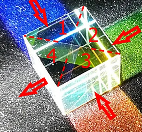
- Using separate monochromatic RGB microLED arrays, combining the 3 arrays using an X-cube dichroic prism. The cube itself is a complex assembly made by joining four right-angle prisms together, each with its own set of coatings, which have to be precisely aligned:
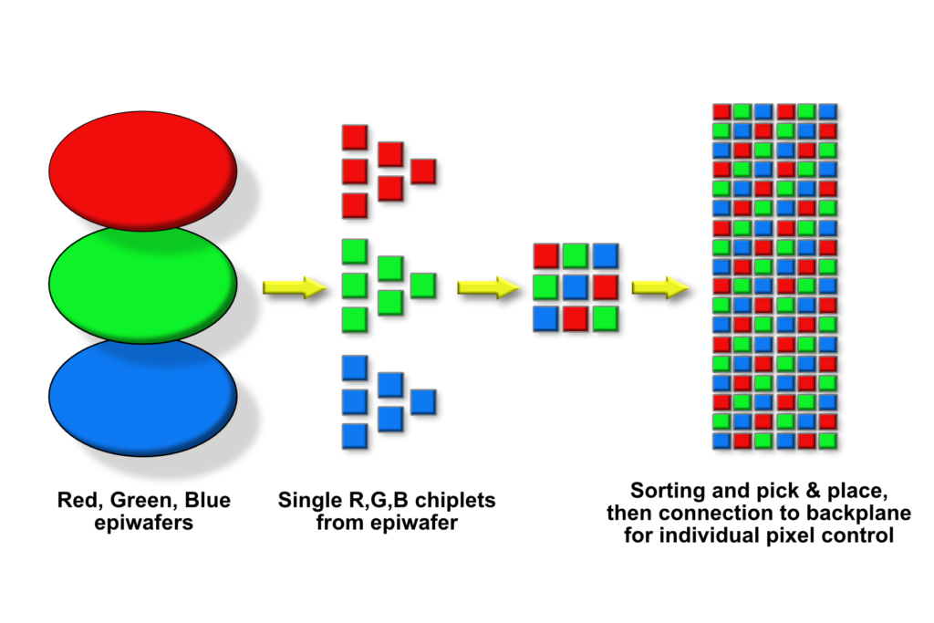
- Integrating separately produced RGB microLEDs onto a single backplane using pick and place:
-
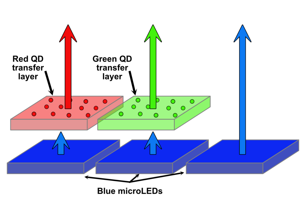
Using a monochrome LED array and adding a color conversion layer (typically quantum dots). This is usually done by using a blue microLED panel, and converting to red and green through he quantum dot layer (blue does not need conversion), see Figure 5.
- Directly growing multi-color microLEDs on the same substrate.
3. LCoS light engines
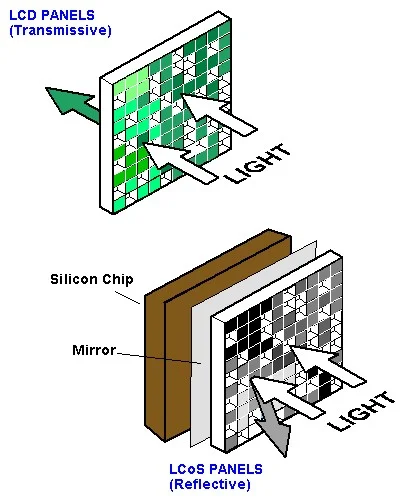
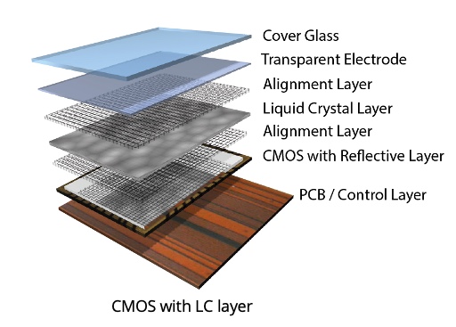
Liquid Crystal on Silicon (LCoS) uses an active matrix liquid crystal display (LCD) on top of a reflective silicon backplane. LCD panels have been around for a long time, and are the basis for most flat- screen televisions/ monitors. LCD panels can be either transmissive or reflective (Figure 6).
Reflective LCoS light engines were initially miniaturized and productized for use in projection systems beginning in the early 2000s, and have advanced rapidly since then. As an example, Google Glass used a reflective LCoS engine back in 2013. [7]
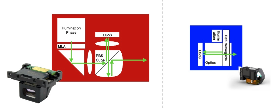
Conventional LCoS architectures use a polarizing beam splitter (PBS) cube to deliver the input illumination to the panel and then project the output to the input coupler of the waveguide. PBS systems are difficult to manufacture and take up valuable volume to the light engine assembly (see section 4.1.1). Additionally, PBS cube architectures have limitations on efficiency and contrast.
Avegant’s LCoS light engines overcome these limitations and manufacturing difficulties. Figure 7 shows the illumination architecture differences between a PBS implementation and Avegant’s much smaller LCoS system.
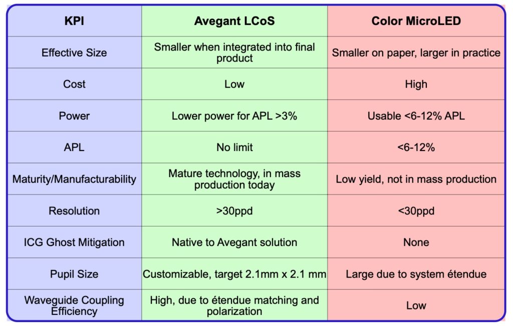
4. Detailed comparison
Avegant LCoS technology versus microLED technology as light engine for AR glasses:
4.1 Effective size:
4.1.1 Size of microLED light engine:
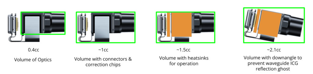
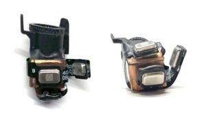
Manufacturers of MicroLEDs often use “small size” as one of their largest selling points. For example, the JBD Hummingbird I polychrome microLED light engine is advertised to have a 0.4cc volume. It is important to note, however, that this 0.4cc volume is just for the light engine optics itself, not the total space claim of the solution, which is typically much larger for the following reasons.
First, these microLED systems require the use of demura memory to correct for the non-uniformity of brightness and color across each of the microLED arrays (see Figure 20). This memory takes up added space (for each of the 3 panels) beyond the light engine itself and results in a large flex cable not represented in the volume measurement.
Second, these systems are very sensitive to heat, and typically require an integrated heatsink with each microLED panel (one each for R,G,B) to improve performance. These heatsinks substantially increase the volume, dimensions and weight required.
Third, microLED panels have very reflective surfaces, which causes ghosts in the image due to reflection from the waveguide input coupler (see Figure 19, up to 20% of the light can be reflected).
The simplest way to reduce this effect is to introduce an angular tilt offset of the AR light engine relative to the input coupler. To avoid ghosts, the angular tilt should approximately be larger than half the Field of View (FOV) being created. So, for a 30° FOV in the AR glasses, a ~>15° tilt has to be introduced to the light engine to waveguide integration, which substantially increases the overall effective volume in glasses.
While the JBD Hummingbird I polychrome system advertises as having a 0.4cc volume, once the above factors are considered , the effective volume of the device can exceed 2cc, more than 5x the original advertised volume as shown in Figure 9. The JBD Hummingbird I is advertised as 640×480 pixel resolution (approximately 26 pixels per degree (PPD)).
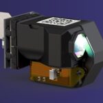
4.1.2 Size of Avegant LCoS light engine
The Avegant AG-30L2 light engine (Figure 11) also has a 30° field of view, is only 1.4cc in total volume, and has higher resolution (720×720 pixels at 34 PPD). Note that the AG-30L2 does not require demura, or heat sinking and it has embedded ghost mitigation
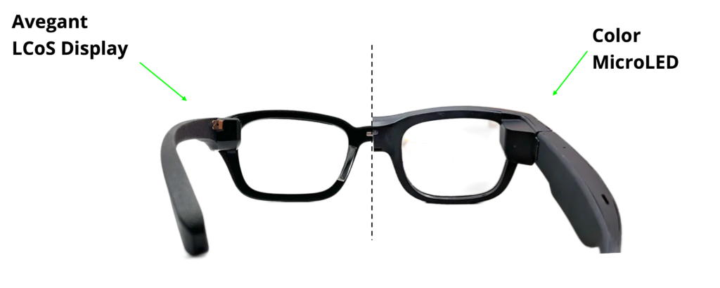
4.1.3 Comparison of LCoS vs. microLED in AR glasses:
LCoS light engines can have a smaller effective size when fully integrated into AR glasses. The image in Figure 12 shows a real-world comparison of two sets of glasses (at the same scale), with the image split to show the difference in size between glasses with Avegant’s LCoS versus a microLED display.
4.2 Efficiency:
Efficiency is very important in AR glasses applications. Efficiency usually refers to “energy conversion efficiency” defined as “the ratio between the useful output of an energy conversion machine and the input, in energy terms” [10]. The luminous efficacy of the light engine is the ratio of input electrical power to the emitted light power at output.
In the case of AR glasses, the energy conversion machine is the light engine and the waveguide, so it is essentially the ratio of light output power delivered to the eye divided by the input electrical power consumed. Critically, the luminous efficacy of the overall system takes into account both the luminous efficacy of the light engine and the efficiency of the waveguide, but it must be viewed as an overall system. In other words, you can not simply multiply the luminous efficacy of the light engine by the luminous efficacy of the waveguide, as factors like the efficiency of the engine to waveguide coupling can have a large impact on the overall system’s luminous efficacy.
4.2.1 Étendue:
To understand the overall system efficiency of an AR display, étendue must be considered as it is a fundamental optical property of these systems. Étendue “is a property of light in an optical system, which characterizes how ‘spread out’ the light is in area and angle” [11]. It is defined as the product of the emitter size and the emitted angle of the light (see Figure 13).
A key concept is that étendue is subject to the law of conservation of energy: the étendue of an optical system will be the same throughout the system, unless some form of loss is introduced (i.e. étendue can not be reduced without losing optical energy). For instance, in the example in Figure 13, the microLED light source could be focused down to a similar projection size as the LCoS by introducing an aperture in front of it, but there will be a huge loss of étendue because only a small amount of the original emitted light can be captured. This can not be resolved through optics.
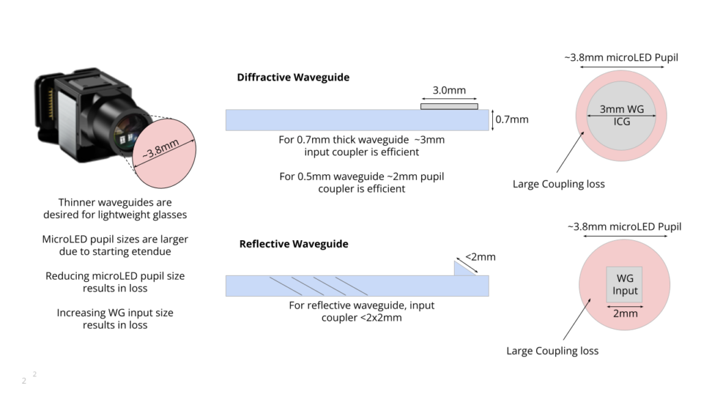
A fundamental issue of all microLED light engines is that they have a large starting étendue by their very nature, for two reasons: 1. The size of the panel (consisting of the array of microLEDs) is large and 2. The individual microLEDs have large emission angles. The étendue is the product of the emitter size and emitted angle of light.
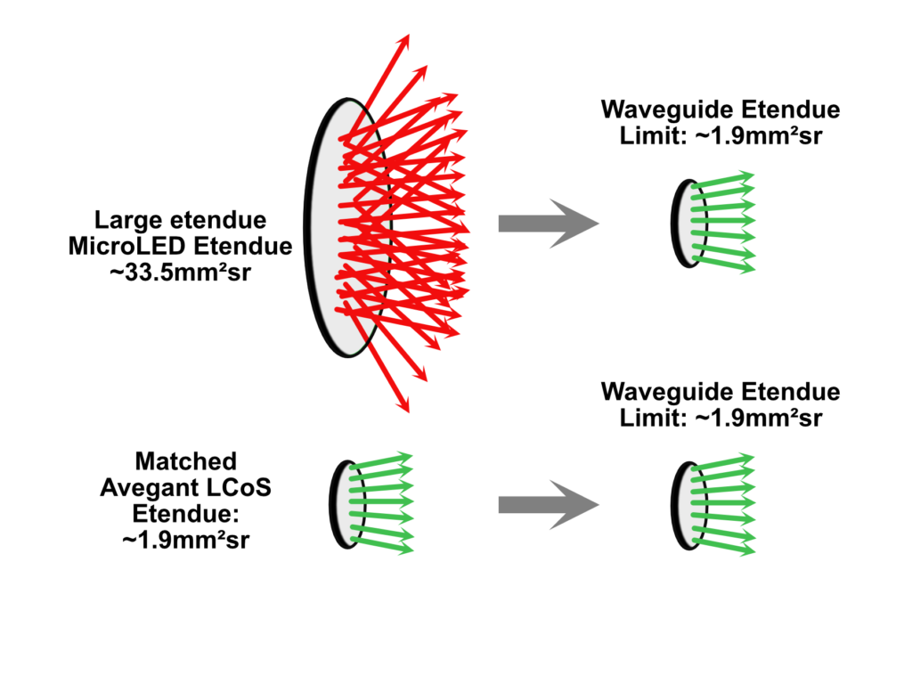
This is not optimal for AR glass systems, as the large starting étendue of microLEDs is much larger than the étendue limit required for waveguides. The input coupling of the waveguide typically has much smaller dimensions and limited angles, causing an immediate loss of étendue from the microLED engine and a significant loss of light. Figures 13 (above) and 14 (below) demonstrate this.
Furthermore, optics cannot reduce the starting étendue as the étendue is created at the point of light generation. Attempts to further shrink the pixel area of the microLED array result in either much lower resolution or smaller pixel sizes that reduce the external quantum efficiency (EQE) of the pixel.
4.2.2 Polarization
Adding to étendue issues, most waveguides are more efficient and have better performance with polarized light. Most waveguides have 20% to 40% coupling loss when non-polarized light is used as the input [12]. MicroLEDs produce unpolarized light, hence suffer from a loss of efficiency due to lack of polarization. Adding a polarizer to a microLED would significantly reduce its efficiency.
4.2.3 Avegant LCoS versus microLED efficiency:
The Avegant LCoS light engine does not suffer from the étendue efficiency losses (see Figure 13) or losses due to polarization as do microLED systems, maintaining high luminous efficacy through the entire system. With LCoS systems, the starting étendue is carefully selected to match the target étendue of the waveguide input coupler, as the LED emitter size (source illumination) has flexibility to change, independent of panel or pixel size. As with any LCoS system, the output light is already polarized before entrance to the glasses waveguide, eliminating coupling loss due to polarization.
4.3 Average Pixel Lit (APL) limitations:
An advantageous property of microLED versus LCoS is that the microLED power consumption is roughly proportional to the Average Pixel Value (APV, also known as Average Pixel Lit = APL) [8]. APL is essentially the average overall output of all pixels in an image as compared to output of a full white image (all pixels fully lit).
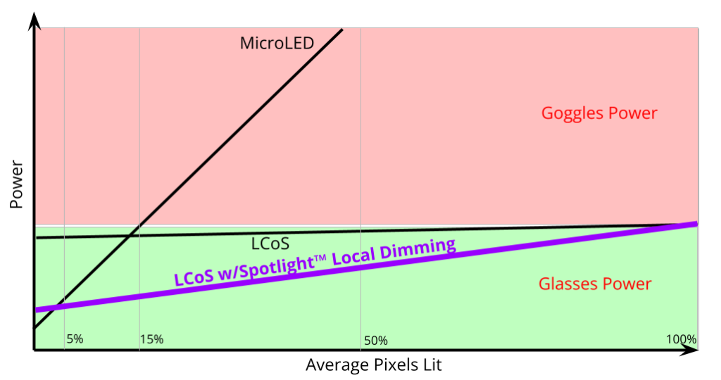
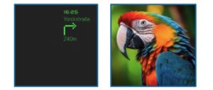
Though optically inefficient, at low APLs microLEDs can consume less power than LCoS light engines. However, at medium APLs microLEDs consume significant amounts of power, above what is typically tolerable for a pair of lightweight AR glasses. And high APLs are not typically possible to display, due to thermal limitations. The power constraints that limit microLED APL prevent most microLED AR glasses from displaying images, photos, or videos, the most sought-after applications for AR glasses.
These APL limitations impact UI/UX and applications for microLED systems. For applications that require higher than 3% APL, Avegant LCoS has a significant power advantage. For example, if we examine the microLED line versus the LCoS line in Figure 15, we can see that as the desired APL goes up, the power required for a microLED increases sharply compared to LCoS. The microLED power consumption exceeds the LCoS power consumption at approximately 6-12% APL.
Additionally, Avegant has introduced a new local-dimming illumination feature called Spotlight™ technology [13]. When used, this greatly reduces the power required for all APLs while also improving the contrast of the image (see the purple line in Figure 15). In this case, at >~3% APL, the LCoS solution requires less power than the microLED solution.
Note the horizontal line in the above graph defining the green region: this represents that there is a limit to the amount of power and thermal dissipation that can be used in a pair of AR glasses. Due to the lightweight nature of AR glasses, there are thermal dissipation limits to displays. The microLED curve crosses over this limit at an APL of 6-12%.
4.4 Challenge of smaller pixel sizes:
In AR displays, there is a continual need to increase the number of pixels into the same size display area in AR glasses. Higher resolution and pixel counts are needed to maintain enough angular resolution for increasing Fields-of-View, which the industry demands. Due to requirements of reducing the light engine size, this results in the reduction of pixel sizes. Avegant’s current state-of-the-art LCoS display engines have 3µm full color pixels, with all three primary colors displayed in a single pixel by temporal modulation.
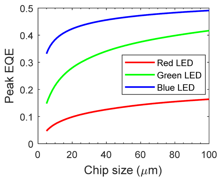
Since microLED systems need to use separate RGB pixels to produce full color display, that same 3µm pixel would actually have to be ~1µm in size to fit all 3 colors into the same size, or ~1.5µm/pixel if deployed as an array. Given the desire to maintain small volume for the light engine itself, the only way to achieve higher resolution is to make the individual pixels smaller. This is a much larger challenge for microLED technology versus the Avegant LCoS approach, especially since microLED EQE falls significantly with smaller pixel sizes (Figure 17). This would also require larger heat sinks as discussed in 4.1.1.
Combining 3 colors onto a single microLED panel by reducing the pixel size results in the same large étendue, but with approximately 1/3rd the emission area and lower EQE, further reducing the efficiency. If the panel area is increased to maintain more efficient larger microLED pixels, the étendue grows, further reducing optical efficiency.
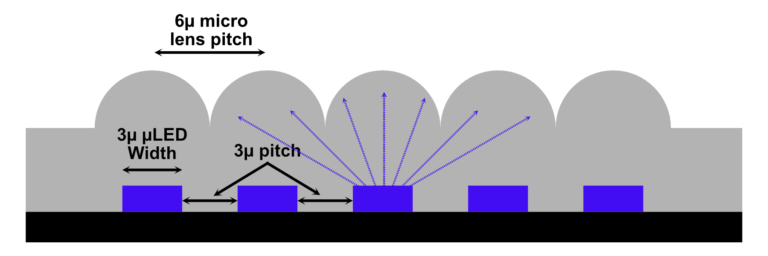
As discussed in 4.2.1, microLED architectures suffer from significant étendue loss due to the large emission area and Lambertian emission angles of the light source. The large emission angles require the use of micro lenses above the LEDs to attempt better capture of the source. However, micro lenses do not change the étendue of the panel, so the fundamental étendue mismatch of the system remains.
These micro lenses need to have a significantly larger pitch than the microLED pitch in order to effectively capture emitted light; in fact, it is recommended that the micro lens pitch should be at least 3x greater than the microLED (pixel) pitch for best efficiency. [15] This makes the overall panel larger than the theoretical size of the panel based on the LED pitch, as shown below in Figure 18.
It is estimated that reducing microLED pixel sizes from 5µm to 2µm would result in a further 40% loss of EQE. Additionally, the micro lenses lose efficacy when the pixel pitch gets smaller.
4.5 Ghost reflections in microLED panels:
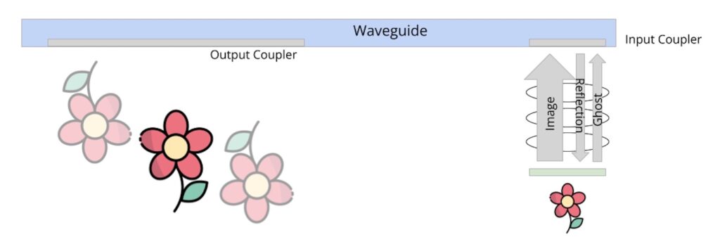
As previously mentioned in section 4.1.1, microLEDs suffer from ghosting caused by the back reflection from the waveguide input coupler to the highly reflective surfaces of the microLED microdisplay panel (Figure 19).
Four methods are available to eliminate this ghosting issue with microLEDs: 1) introduce an angular offset of the microLED engine to the waveguide plane, which increases the overall volume of the glasses, 2) use polarizers to eliminate the ghosting, which causes a further loss of transmitted efficiency, 3) adjust the waveguide pupil shape and size to avoid this reflection, which significantly decreases the coupling efficiency, or 4) create a non-telecentric optical system, which significantly increases the volume of the light engine.
The Avegant AG-30L2 system is architected with built- in ghost mitigation. As a result, no special design considerations are required to mitigate ghost reflections in glasses systems.
5. Cost and manufacturability:
LCoS, being a much more mature technology than microLED, has significantly fewer challenges in manufacturing, and thus is generally less costly and more scalable.
5.1 Challenges producing full color displays:
Avegant LCoS uses single pixel temporal multiplexing to produce RGB images, which is a fairly simple approach. The illumination source time multiplexes the red, green, and blue illumination reflecting off the LCoS panel to produce full color. This is simple to manufacture, resulting in high efficiency, high resolution, and high yield. Liquid Crystal on Silicon backplane manufacturing techniques are very mature, resulting in high yield and low cost. These types of technologies have already shipped hundreds of millions of chips into the market, powering projectors, automotive HUDs, medical, and industrial applications.
MicroLEDs, on the other hand, have significant challenges in producing a full color display. The first challenge is that the actual materials used to produce red, green and blue LEDs are different and typically have incompatible manufacturing processes.
As mentioned in section 2, there are several different ways of producing RGB microLEDs:
- Using 3 separate RGB microLED panels and combining them optically using an X-cube prism (most common, see Figure 3);
- Combining 3 separate colors on the same backplane through die transfer (see Figure 4);
- Using a monochrome source LED and adding a color conversion layer such as quantum dots (see Figure 5); and
- Growing 3 different color LEDs on same substrate.
Method 1, using 3 separate RGB microLED panels and optically combining through a prism is the method used in the JBD Hummingbird I system described earlier in section 4.1.1.
This method is very expensive to implement, being difficult to manufacture, with low yields. It requires 4 separate prisms with multiple optical coatings and extremely precise tolerances and alignment of the prisms, as well as 6-DoF alignment of each individual microLED panel. Any defects in the prism structure are very close to the focal plane of the display and will be visible as a visual artifact.
Method 2 requires very complex manufacturing techniques to transfer separate red, green and blue microLED pixels onto a single substrate. Separate red, green and blue wafers of microLEDs (typically of different materials) are first produced, and only the microLEDs that pass a performance specification can be transferred.
These separate RGB wafers can have varying degrees of yield and performance across the wafer, depending on the individual materials. Once the acceptable individual RGB pixels are identified from each wafer, they need to be passed on to a new wafer and connected electrically to the new backplane.
This is usually done via pick and place (die transfer), although some other methods such as elastomer stamp transfer, laser induced transfer, fluidically self- assembled transfer, electrostatic transfer and roll-to- roll or roll-to-panel imprinting transfer have been investigated [4]. All of these methods suffer from extreme complexity with resulting low yield, and therefore are high-cost by nature.
Method 3 uses a color transfer layer with a monochrome LED, typically using a quantum dot color conversion layer. This method is also very complex and costly, with several challenges including material stability, manufacturing challenges, efficiency, crosstalk, and toxicity concerns.
Method 4, growing 3 different color LEDs on the same substrate has substantial challenges to overcome. These typically involve using GaN based materials to generate all 3 colors and have significant challenges with red emission efficiency, as well as closing the green gap efficiency. Additionally, they are prone to variations in epi growth, which introduces uniformity challenges for microdisplays [16]. As mentioned before in section 4.4, combining 3 colors onto a single panel will result in reduced emission area, larger étendue and/or less effective micro lenses.
5.2 Low yield of microLED systems:
Recognizing the complexity of producing a full color microLED system as discussed above, one also needs to take into account the generally low chip yields seen for single color microLEDs and far lower yields for full color microLEDs.
Mura considerations: As discussed in section 2, even monochrome microLED panels suffer from visible variations in intensity across the entire 2D panel. This is because each pixel is a separate microLED, and it is difficult to produce a wafer of microLEDs having identical intensity, as shown in Figure 20 on right.
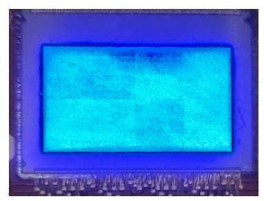
It is important to note that the above panel was made from only “acceptable” microLEDs from the original wafer, so there is low yield to begin with. Because of this variation, the microLED light engine has to include demura memory to correct for the variation, adding cost, heat and size to the engine.
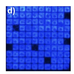
Defective microLEDs: Even after individual pixels of acceptable quality have been taken from the original wafer, some of them can end up being either “dead” or “hot” once placed in the final assembly as shown at right, contributing to the mura issues (see Figure 21, right).
MicroLED color variation: for the same reasons as mura issues highlighted above, the individual pixels on a monochrome microLED panel can have differing colors, adding in variation of color across the field.
These three issues contribute to typical fairly low yield numbers for microLEDs in general. Low yields are the largest single contributor to costs for light engines.
5.3 Higher cost for microLEDs versus LCoS:
While both LCoS and microLED systems have similar backplanes, the LCoS frontplane is significantly less complex and costly than that of microLED’s (see Figure 22). Additionally, the actual process for making an LCoS array is vastly simpler. This results in an inherently less expensive component when comparing LCoS to microLED light engines. This may result in a permanent cost advantage to LCoS. As mentioned above, semiconductor yield is a significant contributor to overall cost of microLEDs. Some may argue that newer manufacturing methods, and economies of scale should bring down the cost of microLEDs, but the fundamental process complexity and low yields will most likely always outweigh those cost savings.
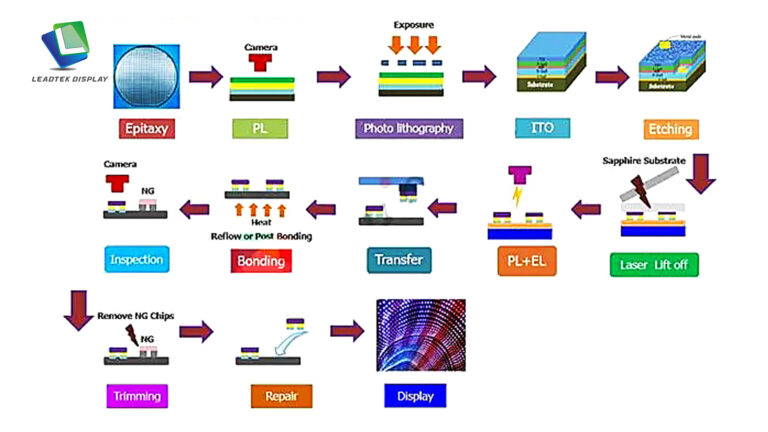
The complexity of the microLED manufacturing process is represented in Figure 23, showing the steps necessary to produce a monochrome microLED display panel using the pick and place method.
Recognize that the process detailed above is only for making the display panel portion of the overall AR light engine. It does not include the optics and additional electronics (demura memory, etc.) which need to be added to complete the light engine.
6. Conclusions:
The key considerations for choosing a light engine for AR glasses are as follows:
- Size: The light engine must be small, using up as little space in the glasses frame as possible. While some microLED solutions promise small size, one must take into account the effective size of the overall package, including all accommodations such as heatsinking, additional connectors and memory chips, integration angles to eliminate ghosts, etc.
- Efficiency: The light engine must maximize the light delivered to the observer through the exit pupil of the waveguide. MicroLED solutions suffer from fundamental low efficiency due to étendue loss, thermal constraints and lack of polarization. The result is that microLEDs are enormously inefficient in comparison to LCoS, thus are limited to low APLs to maintain reasonable power and thermal limits.
- Average Pixel Lit (APL) limitations: Due to the optical inefficiencies of microLEDs, they are limited to very low APLs (<6-12%). This limits the use cases of microLEDs to sparse information, not the images and videos that require higher APL. Avegant LCoS has no APL limitations and can display high APL content without incurring power or thermal issues.
- Smaller pixel size challenges: For continued acceptance of AR glasses, the displays must become higher resolution without growing the light engine size. Avegant LCoS architectures can continue increasing resolution in current form factors, whereas microLED solutions will require technological breakthroughs to exceed current resolutions in the same size form factor without further sacrificing performance.
- “Ghost reflections”: Waveguide input couplers have significant reflection back into the light engine. The high reflectivity of microLED panels produces significant ghosting, which requires a large angle tilt of the microLED engine to avoid. This results in a larger engine chamber in AR glasses, increasing product sizes. Avegant LCoS engines have proprietary internal ghost mitigation, which allows for the smallest volume integration with waveguides.
- Costs and challenges of manufacturing: MicroLED panels face tremendous challenges in manufacturing, with typically small yields adding greatly to price and complexity. Further requirements to shrink pixel size or produce full color microLEDs add to this challenge.
Despite microLEDs garnering significant attention as new display technology, they have many challenges to overcome to be high performance, low cost and high yield for AR Glasses. Avegant’s LCoS technologies produce high performance, small light engines with high yields, taking advantage of well-established manufacturing technologies to produce smaller, low cost, efficient light engines for AR glasses.
To summarize, LCoS is “the display of choice for full-color waveguide AR glasses design” [8].
References:
-
Augmented Reality Glasses. Retrieved April 22, 2025 from https://www.ar.rocks/glossary/augmented-reality-glasses
- What is The Use of Waveguides in AR Glasses? Retrieved April 22, 2025 from https://www.displaymodule.com/blogs/knowledge/optical-see-through-waveguide
- Avegant Corp (2025)
- Wu, Y., Ma, J., Su, P., Zhang, L., & Xia, B. (2020). Full-Color Realization of Micro-LED Displays. Nanomaterials, 10(12), 2482. https://www.mdpi.com/2079-4991/10/12/2482
- CES (Pt. 2), Sony XR, DigiLens, Vuzix, Solos, Xander, EverySight, Mojie, TCL color µLED. Retrieved April 25 from https://kguttag.com/2024/01/24/ces-pt-2-sony-xr-digilens-vuzix-solos-everysight-mojie-tcl-color-%C2%B5led/
- Exploring the Potential of LCoS Microdisplays. Retrieved April 23, 2025 from https://www.azom.com/article.aspx?ArticleID=20844
-
Google Glass (2025, May 29). In Wikipedia. https://en.wikipedia.org/wiki/Google_Glass
- SID Display Week 2024 – LCOS. Retrieved April 21, 2025 from https://kguttag.com/2025/03/06/sid-display-week-2024-lcos/
- History of Augmented Reality. Retrieved April 22, 2025 from https://codereality.net/ar-for-eu-book/chapter/introduction/historyar/
- Energy conversion efficiency. (2025, January 24). In Wikipedia. https://en.wikipedia.org/wiki/Energy_ conversion_efficiency
- Etendue. (2025, March 24). In Wikipedia. https://en.wikipedia.org/wiki/Etendue
- Zhao, Z., Lee, Y. H., Feng, X., Escuti, M. J., Lu, L., & Silverstein, B. (2024). Theoretical efficiency limit of diffractive input couplers in augmented reality waveguides. Optics Express, 32(7), 12340-12357. https://doi.org/10.48550/arXiv.2401.06900
- Gross, A. and Tang, E. (2024), Avegant Spotlight: Developing Segmented Illumination for LCoS. Information Display, 40: 13-18. https://sid.onlinelibrary.wiley.com/doi/10.1002/msid.1499
- Hsiang, E.-L., He, Z., Huang, Y., Gou, F., Lan, Y.- F., & Wu, S.-T. (2020). Improving the Power Efficiency of Micro-LED Displays with Optimized LED Chip Sizes. Crystals, 10(6), 494. https://www.mdpi.com/2073-4352/10/6/494
- Melena, N. W., Wiersma, J. T. “Pixel size requirements for AR/MR,” Proc. SPIE 11765, Optical Architectures for Displays and Sensing in Augmented, Virtual, and Mixed Reality (AR, VR, MR) II, 1176505 (27 March 2021); https://www.spiedigitallibrary.org/conference-proceedings-of-spie/11765/2584168/Pixel-size-requirements-for-ARMR/10.1117/12.2584168.full
- Chen, D., Chen, Y. C., Zeng, G., Zhang, D. W., & Lu, H. L. (2023). Integration Technology of Micro- LED for Next-Generation Display. Research (Washington, D.C.), 6, 0047. https://spj.science.org/doi/10.34133/research.0047
- MicroLED Displays: Measuring and Correcting Uniformity. Retrieved April 25, 2025 from https://www.azooptics.com/Article.aspx?ArticleID=1899
- Herrnsdorf, J., McKendry, J, Zhang, S., Xie, E., Ferreira, R., Massoubre, D., Zuhdi, M., Wafi, A., Henderson, R., Underwood, I., Watson, S., Kelly, A., Gu, E., & Dawson, M. (2015). Active-Matrix GaN Micro Light-Emitting Diode Display With Unprecedented Brightness. IEEE Transactions on Electron Devices. 62. 1-1. https://ieeexplore.ieee.org/document/7084141
- The development history of the display screen. Retrieved April 24, 2025 from https://www.leadtekdisplay.com/the-development-history-of-the-display-screen-a-1019.html
- Lazarev, G., Friedemann, G., & Luberek, J. (2017) Ultrahigh-resolution phase-only LCOS spatial light modulator, Proc. SPIE 10125, Emerging Liquid Crystal Technologies XII, 101250M. https://www.spiedigitallibrary.org/conference-proceedings-of-spie/10125/1/Ultrahigh-resolution-phase-only-LCOS-spatial-light-modulator/10.1117/12.2250531.full