The pursuit of compact augmented reality glasses has often focused on the volume of the light engine as the primary metric of success. However, as we integrated the AG-30L3 into new customer designs, it became clear that the most impactful design decision we made was not just the 0.7cc volume, but the transition to a small 2.1mm pupil.
For display and optics engineers, the light engine and the waveguide must be viewed as a single, coupled system. When we look at the physics of the in-coupling grating (ICG) and the constraints of étendue, the advantages of a smaller pupil become a mathematical certainty.
Optimizing for ICG Peak Efficiency
A common misconception is that the in-coupling grating (ICG) of a diffractive waveguide has uniform efficiency across its area. In reality, the efficiency of the ICG varies significantly based on the spatial position of the incident light. Every grating has a sweet spot where the diffraction efficiency peaks.
When using a standard 3 mm pupil, the light spread covers a larger area of the ICG, including regions where the efficiency drops off significantly. By moving to a 2.1 mm pupil, we concentrate the light flux into the high efficiency region of the ICG where the number of interactions is lower to minimize losses from secondary and tertiary interactions with the ICG.
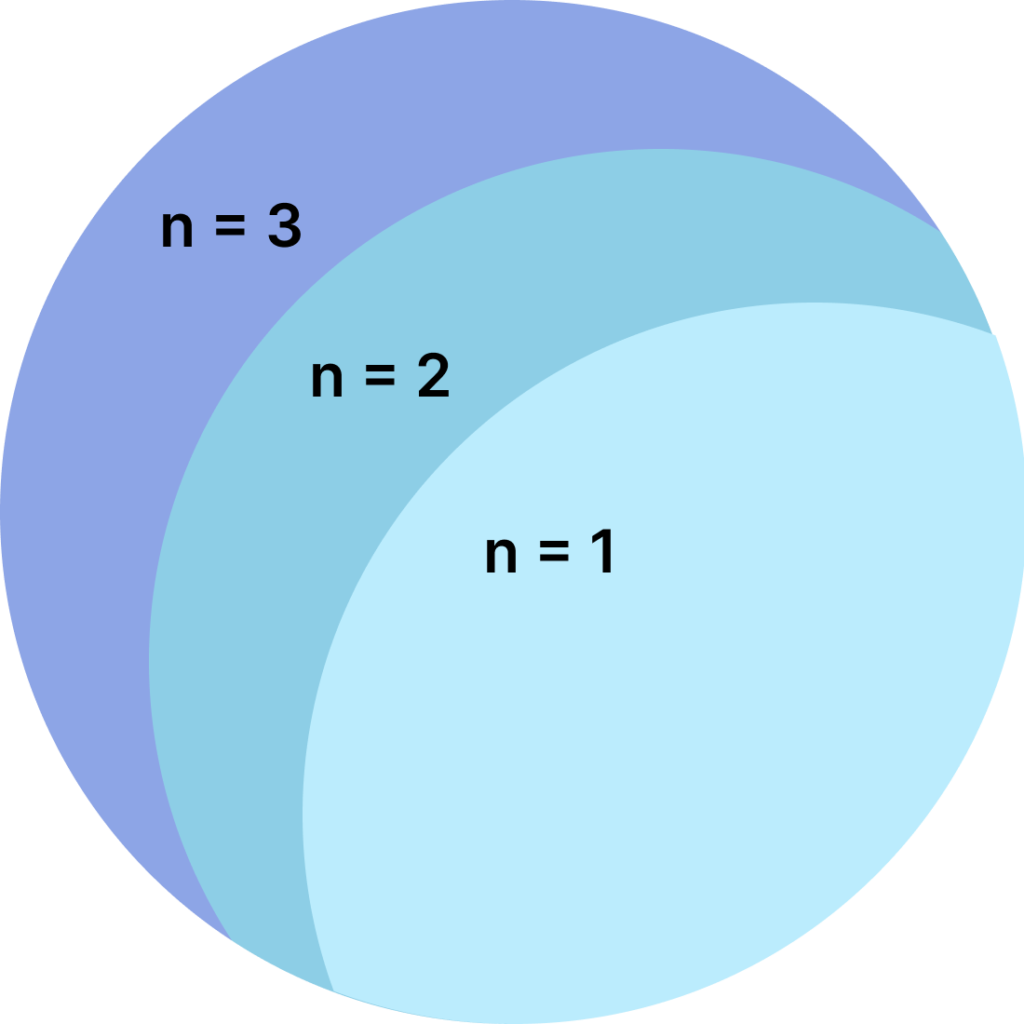
Fig. 1. Input grating efficiency of the waveguide varies spatially as it affects the number of interactions
with the input grating
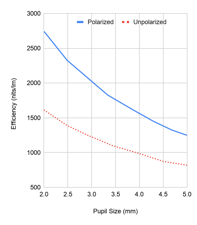
Fig. 2. The efficiency of the waveguide is impacted by pupil size and polarization. This figure shows an example model of a 30° diffractive waveguide.
The results are substantial. By restricting the pupil to 2.1mm, we see an increase in waveguide efficiency of approximately 30% compared to a 3mm pupil and 60% compared to a 4mm pupil. This smaller pupil increases coupling efficiency even for waveguides originally designed for larger pupils, as the light is simply more effectively utilized within the grating architecture.
Enabling 10g Weight Savings via Thinner Waveguides
The physical thickness of the waveguide is the primary driver of headset weight. A typical 0.7mm thick glass waveguide weighs approximately 7g. To achieve a consumer ready form factor, we need to move toward 0.5 to 0.3 mm glass substrates, which weigh as little as 2g. This transition saves 5g per eye, totaling a 10g reduction in weight for the headset.
However, thinning the waveguide creates a challenge with secondary interactions at the ICG. As light travels via Total Internal Reflection (TIR), it must clear the ICG area to continue toward the expansion gratings. In a thin 0.3mm waveguide, the spatial period between TIR bounces is much shorter. If the input pupil is large, rays are far more likely to strike the ICG a second or third time. These secondary interactions cause the light to couple back out of the waveguide rather than propagating forward, leading to significant efficiency losses.
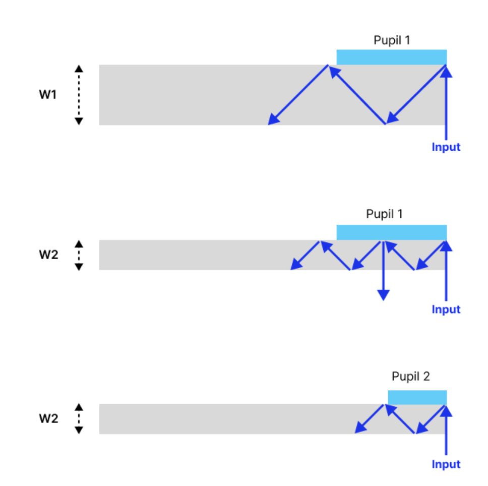
Fig. 3. Simplified view of input grating interactions depending on waveguide thickness. Losses from secondary interactions are observed when the thickness is reduced without reducing the pupil size.
Because the AG-30L3 utilizes a smaller 2.1mm pupil, waveguides can be designed with a smaller pupil enabling thinner waveguides because the coupled light will clear the ICG. This allows engineers to utilize substrate thicknesses down to 0.3mm waveguides while maintaining high efficiency and the weight savings mentioned above.The Étendue Mismatch of microLED
The industry often discusses microLED and LCoS in terms of brightness, but an important factor for display system efficiency is étendue. A waveguide is an étendue limited system defined by the pupil size and the Field of View (FoV). To maximize efficiency, the étendue of the light source should match the étendue of the waveguide. Avegant’s LCoS technology allows us to produce custom LEDs and LED packages designed specifically to perfectly match the étendue of the waveguide. Because we customize the LED source size, we ensure the source étendue is exactly matched to the system’s étendue limit. In contrast, microLED arrays are inherently étendue mismatched because the array is the emission source and its size is dictated by the pixel pitch and resolution requirements. Consider the geometry of a typical microLED panel with an active area of 2.64mm x 2.02mm and Lambertian emission. We calculate the source étendue (E_source) as:Esource = (2.64 × 2.02) · π · sin²(90°) ≈ 16.75 mm²sr
Now, let’s look at the étendue limit (E_limit) for a 30° full FoV (15° half angle) across two different waveguide pupil sizes and compare the geometric efficiency ($\eta_{geo}$): Scenario 1: Standard 3mm Circular PupilArea ≈ 7.07 mm²
- Waveguide Limit:
Elimit = 7.07 · π · sin²(15°) ≈ 1.48 mm²sr
- microLED Étendue Utilization:
ηgeo = 1.48⁄16.75 ≈ 8.8%
- Avegant Étendue Utilization: Since the Avegant LED source is custom sized to match the 1.48 mm²sr limit exactly
ηgeo = 100%
- Comparison: Avegant provides 11.3x the étendue utilization of microLED in this configuration.
Area = 4.41 mm²
Waveguide Limit:Elimit = 4.41 · π · sin²(15°) ≈ 0.93 mm²sr
- microLED Étendue Utilization:
ηgeo = 0.93⁄16.75 ≈ 5.5%
- Avegant Étendue Utilization: Again, by matching the source to the limit,
ηgeo = 100%
- Comparison: Avegant provides 18.1x the geometric efficiency of microLED in this configuration.
The Polarization Bonus
The final piece of the efficiency puzzle is polarization. The majority of high index diffractive waveguides are optimized for a single polarization state. Providing unpolarized light, as is common with microLED, results in a loss because the non-optimized polarization state is either not trapped or is diffracted with very low efficiency. This efficiency difference is highlighted in Fig 2. The AG-30L3 provides a polarized pupil output. By delivering only the polarization state the waveguide is designed to handle, we boost coupling efficiency by approximately 50% compared to an unpolarized source.Cumulative Gains: The New Math of Efficiency
When we combine these factors, the shift to the 2.1mm polarized pupil of the AG-30L3 fundamentally changes the performance profile of the system. This smaller, polarized pupil increases coupling efficiency even for waveguides designed for larger pupils.- Polarization Gain: Approximately +50% coupling efficiency (1.5x)
- Small Pupil ICG Gain: Approximately +50% coupling efficiency (1.5x)